
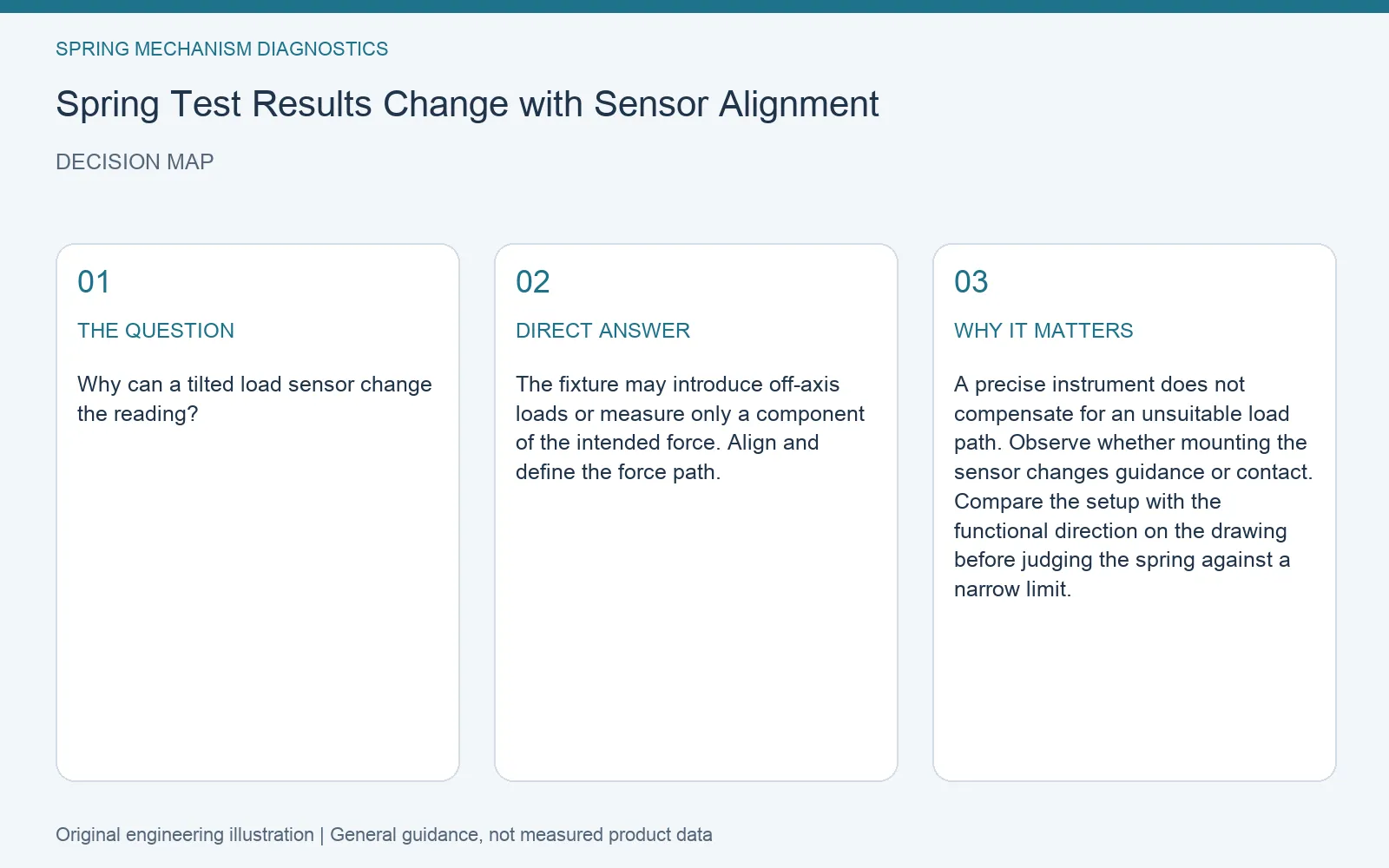
Quick answer: The fixture may introduce off-axis loads or measure only a component of the intended force. Align and define the force path.
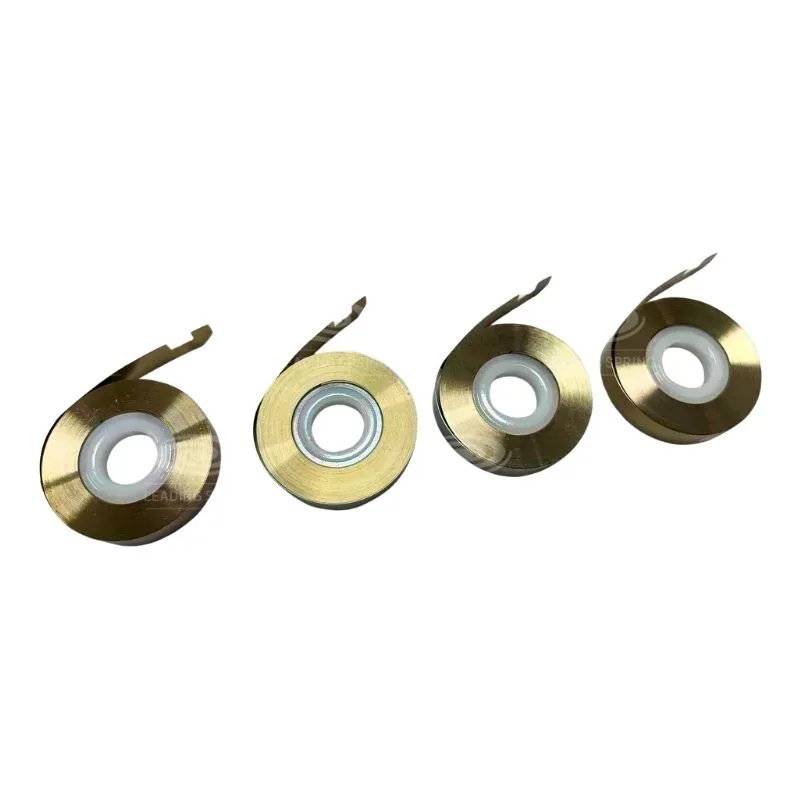
Why can a tilted load sensor change the reading?
A precise instrument does not compensate for an unsuitable load path. Observe whether mounting the sensor changes guidance or contact. Compare the setup with the functional direction on the drawing before judging the spring against a narrow limit.
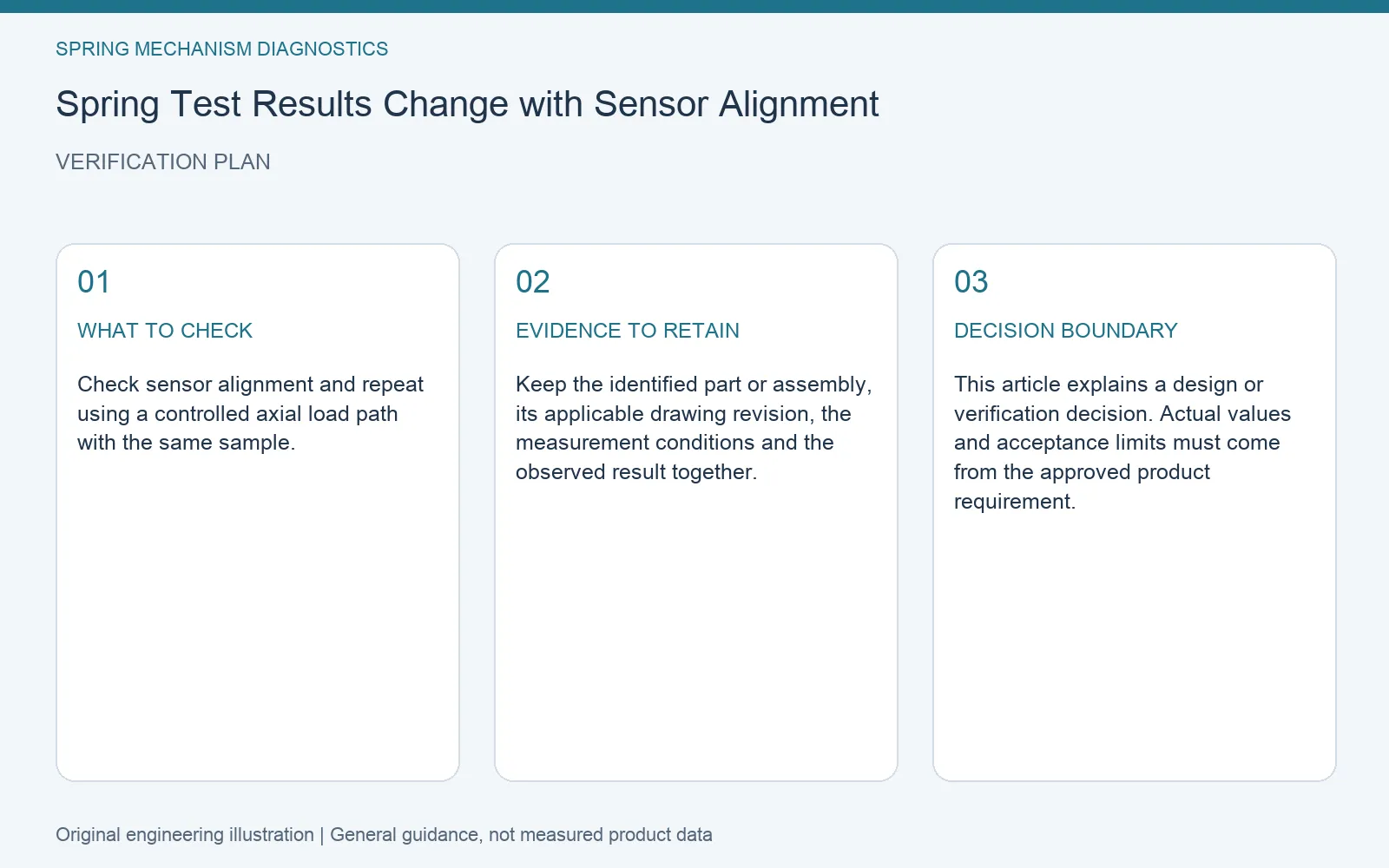
A practical verification method
Check sensor alignment and repeat using a controlled axial load path with the same sample.
| Item | What to record | Purpose |
|---|---|---|
| Reference configuration | Part or assembly identity and drawing revision | Make comparisons traceable |
| Test conditions | Relevant position, direction and operating condition | Compare the same characteristic |
| Decision evidence | Check sensor alignment and repeat using a controlled axial load path with the same sample. | Resolve the specific question before approval |
Use the result in an engineering request
Describe the observed condition and the required function separately. Include the relevant drawing revision and your results from the check above. If an acceptance limit has not been established, identify it as an open design input rather than treating a successful trial as approval.
Review the related Leading Spring product information. For a project-specific review, send the mechanism description, available geometry and the evidence relevant to this decision through the contact page.
Editorial note: AI-assisted engineering guidance, prepared from the topic-specific reasoning shown here and the company’s public product context. Illustrations explain decisions; they are not customer-case photographs or test results. Product-specific suitability requires review against your approved requirements.